Designer | Model visualisation for hazard identification
Description
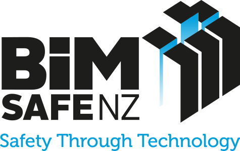
BIM model visualisation during the design phase is a key enabler of Safety in Design processes in construction projects. It involves using Building Information Modelling (BIM) tools to create visual representations of the proposed building, providing the opportunity for hazard identification through virtual walkthroughs, sight line analysis for safety-critical areas, and spatial and task analysis for safe operation and maintenance.
By leveraging these visualisation techniques, design teams can identify, minimise, or eliminate potential safety hazards early in the project lifecycle, supporting the BIMSafe strategy. This proactive approach to hazard identification is particularly cost-effective, as changes to building systems, room layouts, or placement of critical equipment become significantly more expensive if implemented during construction or after building handover. Unlike traditional 2D representations, BIM model visualisation ensures that all stakeholders have access to the same comprehensive, three-dimensional information. This shared visual understanding reduces misinterpretations, improves collaboration, and leads to more informed decision-making and ultimately safer building designs.
Uses and benefits for health and safety
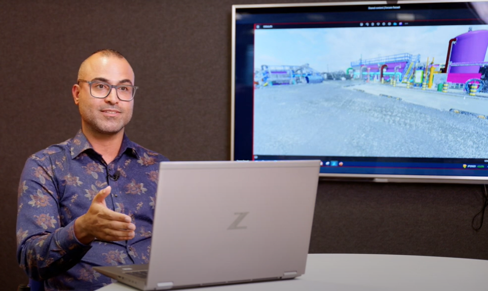
- Allows design teams to navigate through the digital model from various perspectives, including those of future occupants and maintenance personnel, to help identify potential hazards that might not be apparent in 2D drawings, such as awkward maintenance access or poorly placed emergency exits.
- space
- Supports better coordination by integrating different building systems (structural, mechanical, electrical), so teams can identify potential conflicts that could pose safety risks during construction or operation.
- space
- Helps visualisation of different “what-if” scenarios, such as emergency evacuations or equipment replacement procedures, to help design teams anticipate and address potential hazards in different situations, leading to more comprehensive safety planning.
- space
- Supports creation and visualisation of designated safety zones, highlighting areas that require special attention or protective measures. This visual representation helps ensure that safety considerations are integrated into the design from the outset.
- space
- Provides a common platform for all stakeholders to understand and discuss safety issues, driving better design through more informed decision-making and a shared understanding of safety priorities across the project team.
Technology/techniques
Models need to contain an appropriate level of detail for each project stage and strike a balance between visual complexity and clarity of information, avoiding overly cluttered or confusing visualisations. Consistency in representation across different model views is also important for clear communication and understanding among all stakeholders. Techniques to assist in visualisation include colour coding and transparency which can be used to highlight safety-critical elements, such as fire-rated structures or evacuation routes; layering and filtering to simplify complex models by showing or hiding specific building systems or elements; using 3D sectioning and cut planes to view inside walls, floors, and ceilings, and reveal revealing hidden elements that may pose safety risks or require special consideration during maintenance.
Animation and time-lapse visualisation can provide more complex visualisations by animating the construction sequence or building operations to identify safety issues that might occur during different project phases or operational scenarios. Immersive technologies such as virtual reality (VR) and augmented reality (AR) are also available to provide a more intuitive understanding of spatial relationships and potential hazards, but require greater investment in modelling and programming capabilities.
Model/data requirements
To effectively use BIM model visualisation for hazard identification and safety in design processes, the design team should generate models to an agreed level of detail (LOD) for the building elements they are designing. Typically, BIM models at LOD 100 and LOD 200 provide adequate detail for hazard identification during the design phase. These levels offer sufficient information to visualise the overall building form, spatial relationships, and major systems without overwhelming the model with excessive detail.
The models should include key safety-related information such as structural elements, major equipment locations, access routes, and spaces designated for maintenance activities. Data requirements might include properties like fire ratings, material specifications, and equipment dimensions.
Commonly used file formats for model visualisation include Industry Foundation Class (IFC) and Autodesk’s Revit (RVT) format, ensuring interoperability across different software platforms to allow federation of models from different consultants. File conversion software may be necessary if the project requires switching between different formats, ensuring all stakeholders can access and interact with the model regardless of their preferred software.
Hardware and software requirements
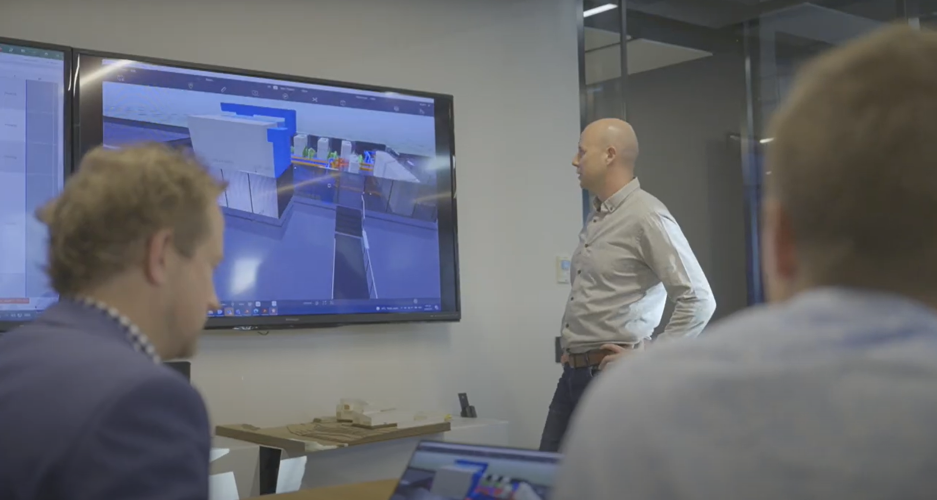
Most modern computers can run basic BIM visualisations, but for optimal performance during design review meetings, high-performance computers with dedicated graphics cards are recommended. These should be connected to large, high-resolution displays or projectors for clear group viewing.
Viewing software comes in two types: locally installed applications, which often offer more features and better performance, and web-based services, which provide greater accessibility and cross-platform compatibility. For enhanced interaction and immersive experiences, virtual reality (VR) setups can be employed, offering stakeholders a more intuitive understanding of the designed space but requiring specialist VR software, headsets and controllers.
BIM visualisation tools allow for both office-based and on-site use and many solutions offer online and offline access. Mobile devices such as tablets and smartphones can access web-based viewing tools, facilitating on-site visualisation. Collaboration software that allows multiple users to view, comment, and mark up the model simultaneously enhances the effectiveness of visualisation in design review meetings.
Contract/procurement implications
The design BIM Brief and BIM Execution Plan (BEP) details how BIM will be used on the project. The BEP is agreed to by the design team and sets out how the BIM models will be developed and used, and what information each model will contain.
Costs for accessing and using model visualisations must be agreed by all parties. Typically, the visualisation software and user allowances are defined in the BEP and contract. The contract can include how the visualisation will be accessed, when it will be updated and how many people can use it.
BIM models can be included in the New Zealand Construction Industry Council’s (NZCIC) guidelines for each design stage of the project. The guidelines are commonly used during the project’s contract and procurement stages.
The contract should clarify that the BIM model is required for health and safety purposes and specify the exact uses, such as reviews and reports carried out by the maintenance teams during each design phase.
Roles and responsibilities
| Design team |
Responsible for integrating safety considerations into the building design and using model visualisation to identify potential hazards, propose design solutions, and document safety-related decisions throughout the design process. |
| Design BIM manager |
Oversees the creation and maintenance of the BIM model, ensuring it contains the necessary information for safety assessments. ㅤ |
| Client/owner |
Defines safety requirements and objectives for the project; participates in design reviews, using BIM visualisations to understand and approve safety measures proposed by the design team. ㅤ |
| Project manager |
Coordinates Safety in Design activities, ensuring they are integrated into the overall project timeline and using model visualisations in team meetings to track progress on hazard mitigation and facilitate decision-making. ㅤ |
Training requirements
BIM modellers from the design team will have minimal training needs as they should already be familiar and proficient with all the applications of the BIM software in use. Clients and non-technical stakeholders may benefit from basic training in navigating BIM viewers and interpreting safety-related visualisations to enable them to actively participate in safety reviews and make informed decisions.
Future directions
Augmented reality (AR) and virtual reality (VR) continue to become more widely available and easier to use, offering immersive experiences that allow stakeholders to interact with designs in a more intuitive manner. Artificial intelligence (AI) and machine learning algorithms are starting to be integrated into BIM platforms, automating the process of identifying potential hazards and suggesting safety improvements.