ACC Ōtepoti: Collaborative use of BIM in safety planning for foundation reinforcing
Summary
On the ACC Ōtepoti project, consultants and contractors have collaborated using BIM to improve safety planning, particularly for the complex reinforced concrete foundation beams. By using 3D models to visualise the dense reinforcement, coordinate the penetrations, and assess the prefabrication opportunities, the project team has been able to reduce manual handling risks, improve the quality of the work, and streamline the construction process.
Background
“The 3D element really brings it to life”
Blair Collie, Senior Project Manager, RCP
The ACC Ōtepoti project is a new office building for the Accident Compensation Corporation (ACC) in Dunedin, New Zealand. The project is a joint venture between Ngāi Tahu Property and ACC.
The building area is 8,000 square meters over four storeys. The project is located between Dowling Street and Queens Gardens, a site with historical and cultural significance for Dunedin and Ngāi Tahu. The project has encountered a number of challenges, such as complex site conditions (including archaeological finds and neighbouring historic buildings), seismic requirements, a tight schedule, and the COVID-19 pandemic.
Naylor Love is the main contractor for the project, with Steel and Tube providing the reinforcing steel. RCP is the client Project Manager, and David Brown (DBC) the services contractor.
One of the early challenges of the project was the complex reinforced concrete foundation beams, which have a high density of reinforcement and require careful coordination with the services penetrations. The project team decided to use BIM to collaborate on the design and construction of these beams, with the goal of improving safety, quality, and efficiency.
Video
Approach
The project team used BIM to collaboratively review the design of the foundation beams and assess the constructability and prefabrication opportunities. Specific examples include:
The reinforcing sub-contractor, Steel & Tube, provided a detailed 3D model of the reinforcement, which allowed the team to visualise the density and complexity of the bars in a way that was not possible with 2D plans and sections. Blair Collie, Client-side Project Manager noted that the model enabled the team to “really dive in and sit around the table and look at those elements” and “pull it apart and look at it from a buildability point of view.”
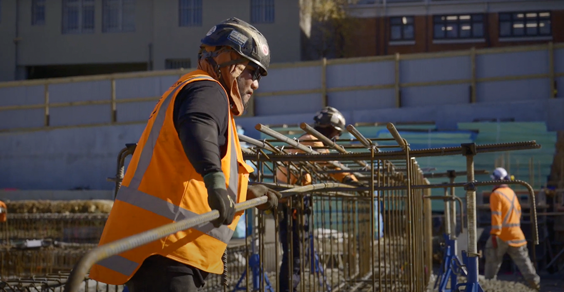
Using the 3D model, the team could plan the best way to work with the heavy 25mm bars and assess which sections were best for prefabrication versus in-situ fabrication. By prefabricating reinforcement cages on stands, workers had a more ergonomic set-up for tying the steel, without awkward bending and balancing on uneven surfaces. The team was able to reduce the amount of manual handling required on site, as the workers could avoid “trying to jump inside the formwork and inside the shutters” to tie the bars, and the crane could be used to place prefabricated sections of reinforcing
The services contractor, DBC, modelled the drainage penetrations through the foundation beams in Revit and shared the information with the team via a federated IFC model. This allowed the team to create bespoke details for the penetrations ahead of time and incorporate them into the prefabricated cages, rather than having to “crawl around on the forms and create these penetrations, dragging extra stirrups and lap bars” on site.
Outcomes and benefits
Health and safety benefits
- Reduced manual handling risks: By prefabricating the reinforcement cages and incorporating the services penetrations off-site, the team was able to reduce the amount of manual handling required on site, particularly the need for workers to climb inside the formwork and manipulate heavy bars in awkward positions. The risk of strain and sprain injuries is significantly reduced through this approach.
Other benefits
- Improved quality: By using 3D models to coordinate the design and prefabrication of the foundation beams, the team was able to achieve a “manifestly better result” in terms of the accuracy and consistency of the reinforcement and penetrations.
- Increased efficiency: By planning the construction sequence and logistics using the BIM model, the team was able to streamline the process and reduce the time required for on-site fabrication and installation. Naylor Love BIM Manager, Mari Richtmann noted, “if we get that right in the model, we get it right on the shop drawings, we get it right in the manufacturing, we get it right on site.”
Lessons learnt
Collaborative BIM is key
The success of the project relied on the collaboration of multiple consultants using BIM, including the structural engineer, contractor, steel fabricator, and services contractor. By sharing information and coordinating their efforts through a federated model, the team was able to identify and resolve issues early and optimise the design for safety and constructability.
3D visualisation enhances understanding
The use of 3D models was critical for visualising the complex reinforcement and penetrations in the foundation beams, which was not possible with 2D plans and sections. Blair Collie, Senior Project Manager RCP commented, “the 3D element really brings it to life” and allows the team to “look at it in a huge amount of detail.”
Prefabrication improves safety and quality
By incorporating the services penetrations early in the process and increasing the amount of prefabrication that could be carried out, the team was able to reduce manual handling risks, improve the quality of the work, and increase efficiency. Naylor Love Project Manager Matt Soppit observed, “the more that they can pre-tie or tie in a controlled environment on stands reduces the manual handling aspect of it on site.”

